
CONDITION MONITORING OF STRUCTURES - PART 1: GENERAL GUIDELINES
WORKING DRAFT 3, DEC 2000, ISO/WD 16587-1.3by John Maguire, Lloyd's Register, Technical Investigation Department
|
|
CONDITION MONITORING OF STRUCTURES - PART 1: GENERAL GUIDELINESWORKING DRAFT 3, DEC 2000, ISO/WD 16587-1.3by John Maguire, Lloyd's Register, Technical Investigation Department |
Warning
This document is not an ISO International Standard. It is distributed for review and comment. It is subject to change without notice and may not be referred to as an International Standard.
Recipients of this document are invited to submit, with their comments, notification of any relevant patent rights of which they are aware and to provide supporting documentation.
Copyright notice
This ISO document is a working draft and is copyright-protected by ISO. While the reproduction of working drafts or committee drafts in any form for use by participants in the ISO standards development process is permitted without prior permission from ISO, neither this document nor any extract from it may be reproduced, stored or transmitted in any form for any other purpose without prior written permission from ISO.
Requests for permission to reproduce this document for the purpose of selling it should be addressed as shown below or to ISO's member body in the country of the requester:
Standards Secretariat
Acoustical Society of America
120 Wall Street, 32nd Floor
New York, New York 10005-3993, USA
Telephone: (212) 248-0373, Fax: (212) 248-0146
Email: asastds@aip.org
Reproduction for sales purposes may be subject to royalty payments or a licensing agreement.
Violators may be prosecuted.
1 SCOPE
2 NORMATIVE REFERENCE(S)
3 TERM(S) AND DEFINITION(S)
3.1 DEFECT (IN A STRUCTURE)
3.2 FAILURE (OF A STRUCTURE)
3.3 PERFORMANCE (OF A STRUCTURE)
3.4 BASELINE
3.5 STRUCTURE (STATIONARY)
3.6 BUILDING
3.7 BRIDGE
3.8 DAM
3.9 OTHER STRUCTURES
4 MONITORED PARAMETERS AND LIMITS
4.1 TYPE OF PARAMETERS
4.2 TYPE OF MEASUREMENT
4.3 ACCURACY OF MONITORED PARAMETERS
4.4 SOURCES OF ERROR
4.5 LIMITS
5 MEASUREMENT PROCEDURE AND DATA PROCESSING
5.1 MEASUREMENT TECHNIQUE
5.2 FEASIBILITY OF MEASUREMENT
5.3 ENVIRONMENTAL CONDITIONS DURING MEASUREMENTS
5.4 DATA ACQUISITION RATE
5.5 RECORD OF MONITORED PARAMETERS
5.6 MEASUREMENT LOCATIONS
5.7 FURTHER DETAILS
6 DEFECT DIAGNOSIS
6.1 PROCEDURE FOR DEFECT DIAGNOSIS
6.2 CRITERIA FOR DEFECT DIAGNOSIS
Annexes A, B and C
ISO (the International Organization for Standardization) is a worldwide federation of national standards bodies (ISO member bodies). The work of preparing International Standards is normally carried out through ISO technical committees. Each member body interested in a subject for which a technical committee has been established has the right to be represented on that committee. International organizations, governmental and non-governmental, in liaison with ISO, also take part in the work. ISO collaborates closely with the International Electrotechnical Commission (IEC) on all matters of electrotechnical standardization.
International Standards are drafted in accordance with the rules given in the ISO/IEC Directives, Part 3.
Draft International Standards adopted by the technical committees are circulated to the member bodies for voting. Publication as an International Standard requires approval by at least 75 % of the member bodies casting a vote.
Attention is drawn to the possibility that some of the elements of this part of ISO 16587 may be the subject of patent rights. ISO shall not be held responsible for identifying any or all such patent rights.
International Standard ISO 16587-1 was prepared by Technical Committee ISO/TC 108, Mechanical Vibration and Shock.
This third draft cancels and replaces the second draft which has been technically revised.
ISO 16587 consists of the following parts, under the general title Condition Monitoring of Structures:
- Part 1: General Guidelines;
- Part 2: Detailed Methods (precise title yet to be decided- document reference ISO 18430).
ISO 16587 also makes reference to two Signal Processing standards under development, namely:
- ISO 18431 - Stationary mechanical vibration;
- ISO 18432 - Non-stationary mechanical vibration.
This standard provides general guidelines for condition monitoring of structures, using parameters typically used to measure or monitor structure performance, such as displacement, strain, vibration, settlement and rotation. The scope covers:
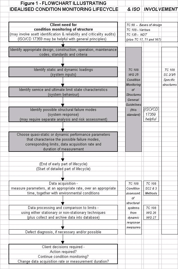
This standard has been organised and written to be consistent with ISO/DIS 13380 - Condition Monitoring of Machinery, Using Performance Parameters, and ISO/CD 17359 - Condition Monitoring of Machinery, General Guidelines, in order to facilitate a consistent approach to condition monitoring of systems. This standard links in with other ISO work as shown in FIGURE 1 below.
This standard presupposes that a "high level" need for condition monitoring of structures already exists. Some useful guidance on identifying this need, by the use of asset identification and reliability/criticality audits, is contained in ISO/CD 17359 - Condition Monitoring of Machinery, General Guidelines.
The target industries for this standard include:
The type of structure covered by this standard include:
This standard describes the general conditions and procedures for recording, assessment, evaluation and diagnostics of structure condition by the regular measurement of parameters related to structure performance. The Introduction to this standard provides further explanation of the scope.
The procedures relate to in-service monitoring of structures, and include all components and sub-assemblies necessary to provide the functioning of the structure as a complete entity. The monitoring is intended to be ongoing in nature through the lifecycle of the structure, as shown in FIGURE 1.
The following normative documents contain provisions which, through reference in this text, constitute provisions of this International Standard. For dated references, subsequent amendments to, or revisions of, any of these publications do not apply. However, parties to agreements based on this International Standard are encouraged to investigate the possibility of applying the most recent editions of the normative documents indicated below. For undated references, the latest edition of the normative document referred to applies. Members of ISO and IEC maintain registers of currently valid International Standards.
There are no directly related normative references at present but see the Introduction and Figure 1 for details of related documents.
For the purpose of this International Standard, the following apply.
A structural defect occurs when the condition of any of its components or their assembly is degraded or exhibits an abnormal behaviour. This may lead to failure of the structure.
The failure of a structure occurs when one or more of the principle functions of the structure are no longer available. This generally happens when one or more of its components is in a defective condition, either at a service or ultimate limit state.
Performance of a structure is defined by one or more characteristic quantities such as displacement, strain, vibration, settlement and rotation. Performance is derived by measurement and calculation of one or more parameters which singly or together provide information on the characteristic quantity.
Parameters, or derived quantities, made under specific loading configurations and specified environmental conditions may be stored or kept as reference values or characteristic profiles. These reference values are called baselines.
A structure is classified here as a stationary engineering artefact, for example as:
Structures excluded from this standard are non-stationary structures, such as self-propelled ships, and mobile structures, such as offshore jack-up platforms.
A permanent built structure that people can go into.
A structure built over and across a river, railway or road, etc., to allow people, road or rail traffic to cross it.
A wall built to hold water back.
To be included in due course - such as towers, masts, antennas, tanks, silos, retaining walls, tunnels, ship hulls, aircraft structural components.
A large range of performance parameters may be measured for purposes of establishing performance criteria, both for acceptance testing and for through life monitoring. The parameters to be considered are those which will indicate a defect condition either by an increase or decrease in overall measured value, or by some other change to a characteristic value. The parameters may be either quasi-static (relatively slowly varying with time) or dynamic (relatively rapidly varying with time) in nature. The parameters may be identified with the assistance of reliability/criticality audits.
Condition monitoring of structures will usually be carried out at serviceability limit state. Any extrapolation to ultimate limit state performance needs careful consideration.
Measured parameters may be simple measurements of overall values, or values averaged over time. For certain parameters, such as strain and vibration, simple measurement of overall values may not be sufficient to show the occurrence of a defect. Techniques such as spectral and phase measurement may be required to reveal changes caused by defects.
Examples of performance parameters useful to consider for a number of structure types are given in ANNEX A.
Condition monitoring systems may take many forms. They may utilise permanently installed, semi-permanent or portable measuring instrumentation, or involve methods for remote or local analysis.
The accuracy required of measured parameters to be used for structure condition monitoring and diagnosis is not so absolute as the accuracy which may be required for performance measurement. Methods utilising trending of values can be effective, where repeatability of measurement is more important than absolute accuracy of measurement. Correction of measured parameters, for example to ISO standard conditions of pressure and temperature, is not necessarily required for routine condition monitoring. Where this is required, advice is given in the appropriate acceptance testing standard.
Measured values and baselines may change due to maintenance work including component change, adjustment or duty change. In certain cases the baseline may need to re-established following such changes.
It should be noted that changes in measured values may also be due to normal or controlled changes in the operating conditions, and not necessarily indicate a defective condition.
As may be seen from Figure 1, the acceptable limits will need to be chosen, by suitably experienced personnel, based on the:
For the particular measurable parameter considered applicable, one or more measurement techniques may be appropriate. The particular technique chosen then needs to be assessed as to the practicalities of implementation, and the type of condition monitoring system required. This topic is addressed further in Part 2 of this standard (see Figure 1, detailed part of lifecycle).
Consideration should be given to the feasibility of acquiring the measurement including ease of access, complexity of required data acquisition system, level of required data processing, safety requirements, cost, and whether surveillance or control systems exist which are already measuring parameters of interest.
Measurements of different parameters should be taken wherever possible at the same time, or under the same environmental conditions. For variable loadings (duty), it may be possible to achieve similar measurement conditions by varying the extent, speed and/or density of the loading.
Monitoring should be taken where possible when the structure has reached a predetermined set of environmental conditions (e.g. seasonal midday temperature). These are also conditions which may be used for a specific structure configuration to establish baselines. Many engineering structures and their baseline parameters show a very strong dependency on temperature, hence measurements should either be taken at the same temperature conditions or the dependency of the baseline parameters on temperature should be known. Subsequent measurements are compared to the baseline values to detect changes. The trending of measurements is useful in highlighting the development of defects.
For steady state conditions, the data acquisition rate should be fast enough to capture a complete set of data before conditions change. During transients, high speed data acquisition may be necessary. Consideration should also be given to the duration of the measurement, the interval between measurements, and whether periodic or continuous sampling is required. A preliminary estimate will need to be made, based on an analysis of how the structure is likely to perform, and the type of defects and their rate of propagation. Subsequently the duration may need to be revised as the monitoring proceeds, if the structural performance differs significantly from that anticipated.
Records of monitored parameters should include as a minimum the following information: essential data describing the structure, the measurement position, the measured quantity units and processing, and date and time information. Other information useful to allow comparison includes details of the measuring systems used and the accuracy of each measuring system. It is recommended that details of structure configuration and any component changes are also included.
Measurement locations should be chosen to give the best possibility of defect location. Measurement points should be identified uniquely. The use of a permanent label, or identification mark, is recommended.
Factors to take into consideration are:
More detailed guidance on the above topics is being prepared by other ISO/TC108 Working Groups as follows:
The possibility of carrying out defect diagnosis will depend on the structure type, configuration and environmental conditions. A defect may be indicated by a change in one or more of the baseline values.
The following criteria may be used to perform defect diagnosis:
As and when circumstances permit, examples of structure type and defects shown by performance parameter monitoring may be included in this standard. Until such time, defect parameter identification may be found using experience, numerical modelling or results of operation, and the interpretation agreed between the builder (constructor) and the owner (operator).
| Performance Parameter | Suitable Structures | Suitable Load Conditions | Instrumentation Systems | Types of Equipment | Remarks |
| Displacement | No restriction | Static, Dynamic | Linear Voltage Displacement Transducer (LVDT) | Electrical | Rigid mounting required |
| Displacement | No restriction | Static, Dynamic | Deflection Pole | Electrical | Quick to set up, very efficient data recording |
| Displacement | No restriction | Static | Dial Gauge | Mechanical | Manual reading and rigid mounting required |
| Displacement related | No restriction | Static, Dynamic | Laser Theodolite Systems | Laser | Good for two dimensional displacement |
| Strain | No restriction | Static | Vibrating Wire (VW) Strain Gauge | Acoustic | Easy to glue to any surface, accurate, can be temperature sensing |
| Strain | Metal, Concrete | Static, Dynamic | Electrical Resistance (ER) Strain Gauge | Electrical | Accurate and reliable but costly; requires special skills |
| Strain | Masonry, Metal, Timber | Static, Dynamic | Demountable ER Strain Gauge | Electrical | Accurate and reliable but not widely used |
| Strain | Metal | Static, Dynamic | Mobile Strain Transducer | Electrical | Used in configuration with deflection pole system |
| Strain | No restriction | Static | Demec Gauge | Mechanical | Easy to use but human error can be significant |
| Vibration | No restriction | Dynamic | Accelerometers | Electrical | Accurate if used correctly |
| Temperature | No restriction | Static, Dynamic | Thermocouples | Electrical | Easy to make and use on site |
| Stress wave (acoustic emission) | Metal | Static, Dynamic | Acoustic Emission Monitoring | Electrical | Requires special skills |
The following standards contain information on reliability analysis and procedures.
BS ISO 2382-14: 1978, Information technology. Vocabulary. Reliability, maintenance and availability.
BS 5760 Part 0: 1986, Reliability of systems, equipment and components. Introductory Guide to Reliability.
BS 5760 Part 1: 1996, Reliability of systems, equipment and components. Dependability Programme Elements & Tasks
BS 5760 Part 2: 1994, Guide to the assessment of Reliability.
BS 5760 Part 3: 1982, Guide to reliability practices: examples.
BS 5760 Part 4: 1986, Guide to specification clauses relating to the achievement and development of reliability.
BS 5760 Part 5: 1991, Guide to failure modes, effect and criticality analysis (FMEA and FMECA).
BS 5760 Part 6: 1991, Guide to programmes for reliability growth.
BS 5760 Part 7: 1991, Guide to Fault Tree Analysis.
BS 5760 Part 8: 1998, Guide to assessment of reliability of systems containing software.
BS EN 61078: 1994, Guide to the block diagram technique.
BS 5760 Part 10, Section 10.5:1993 Guide to Reliability testing. Compliance test plans for success ratio.
BS 5760 Part 11: 1994, Collection of reliability, availability, maintainability and availability predictions.
BS 5760 Part 12: 1993, Guide to the presentation of reliability, maintainability and availability prediction.
BS 5760 Part 23: 1997, Guide to life cycle costing
HB 10007, Reliability, Maintainability and Risk (BSI Handbook).