
NEWSLETTER
Crack Growth Monitoring
|
|
NEWSLETTERCrack Growth Monitoring |
What is monitoring, and why do it?
Crack growth monitoring is where a sequence of crack depths and/or lengths are measured at the same point over a period of time.
It is often used in a test laboratory to provide data on fatigue resistance of a material under given conditions (e.g. environment, load, geometry etc.). In these tests the components can be standard defined geometries (such as compact tension or tensile test specimens) or small pieces representative of a larger structure (such as T-butt welds or tubular intersections).
Crack monitoring can also be required on-site to give early warning of crack initiation in a critical area, for example, or to monitor a known defect up to the point where a failure may be imminent allowing repair to be scheduled at a convenient time (i.e. at a planned shut-down rather than an emergency one).
Crack monitoring uses permanently installed sensors making it more convenient than repeated inspection, especially in areas of difficult access such as high temperature or radioactive environments, underwater or under lagging. Once installed, the use of long cables to the instrument means that the operator does not have to approach the test site. Permanently installed sensors allow crack size measurements to be made as often as necessary on an automated basis without the need for an operator. Since fixed sensors are necessarily always in the same place, they also provide much more repeatable results allowing measurement of small increments in crack growth.
What can TSC offer?
TSC can provide systems to carry out crack monitoring using either the a.c. potential drop (ACPD) technique, or the a.c. field measurement (ACFM) technique. Refer to other TSC literature for further information on these two techniques http://www.tscinspctionsystems.com . Both systems use the Model U10 Crack Microgauge instrument and Flair software to provide crack size (length and depth) as a function of position on the test site (i.e. crack profile) and of time (i.e. a crack growth curve). Cable lengths between the test site and the instrument can be up to 20m.
The pros and cons of the two techniques for crack monitoring are summarised in the following table:
ACPD - Pros
ACPD - Cons
ACFM - Pros
ACFM - Cons
By using permanently installed sensors, and ratios of two voltage measurements to compensate for drift in instrument settings or environmental effects, both techniques can give an accuracy in measurement of incremental growth of around 0.01mm or 0.1%. It should be noted that absolute accuracy of crack depth is lower than this because of variations in probe spacing, pick-up signals etc. Normal absolute accuracy of an isolated measurement on an existing crack is typically 10%. However, if it can be assumed that initial crack depth is zero (or if the depth of a pre-crack can be measured precisely), absolute accuracy can be as high as incremental accuracy.
Examples of Usage
 |
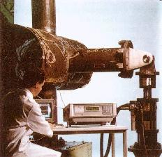
Crack monitoring by ACPD has been used in laboratory situations for most standard fatigue test specimens (CT, tensile, 3-point bend etc.) as well as larger test pieces, such as tubular welded joints. These applications have included testing in corrosion cells containing sea water. Conventionally, these test use multiple spot-welded test points, but in the clean, dry conditions of a laboratory, it has also been possible to use sprung contact points driven across a flat sample by stepper motor. By using special materials in the construction of the contacts, housing and wiring, crack monitoring with both ACPD and ACFM has been carried out in hostile environments including high temperature (pipework at 600oC under lagging), and high radioactivity. |
|
|
|
Future Uses
| Other potential applications that have been discussed have included monitoring critical areas underwater on offshore structures, or monitoring on unmanned offshore installations. This would be done using ACFM sensor arrays to avoid problems of loss of contact, and would use new waterproof instrumentation. Monitoring of underwater sites could be achieved either by fitting signal boosters to allow the voltages to be read by an instrument above water, or by developing an unconnected system which is activated and interrogated periodically (by diver or ROV) using wet-mateable power/comms connections. | 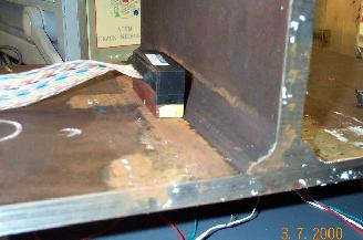 |
|
|
|
 |
|
Contact Details: Dr. Martin Lugg martinl@tscinspectionsystems.com |